3–B superstructure
Building the superstructure
Translating 3D models into 2D plans and building the physical structure.
Published

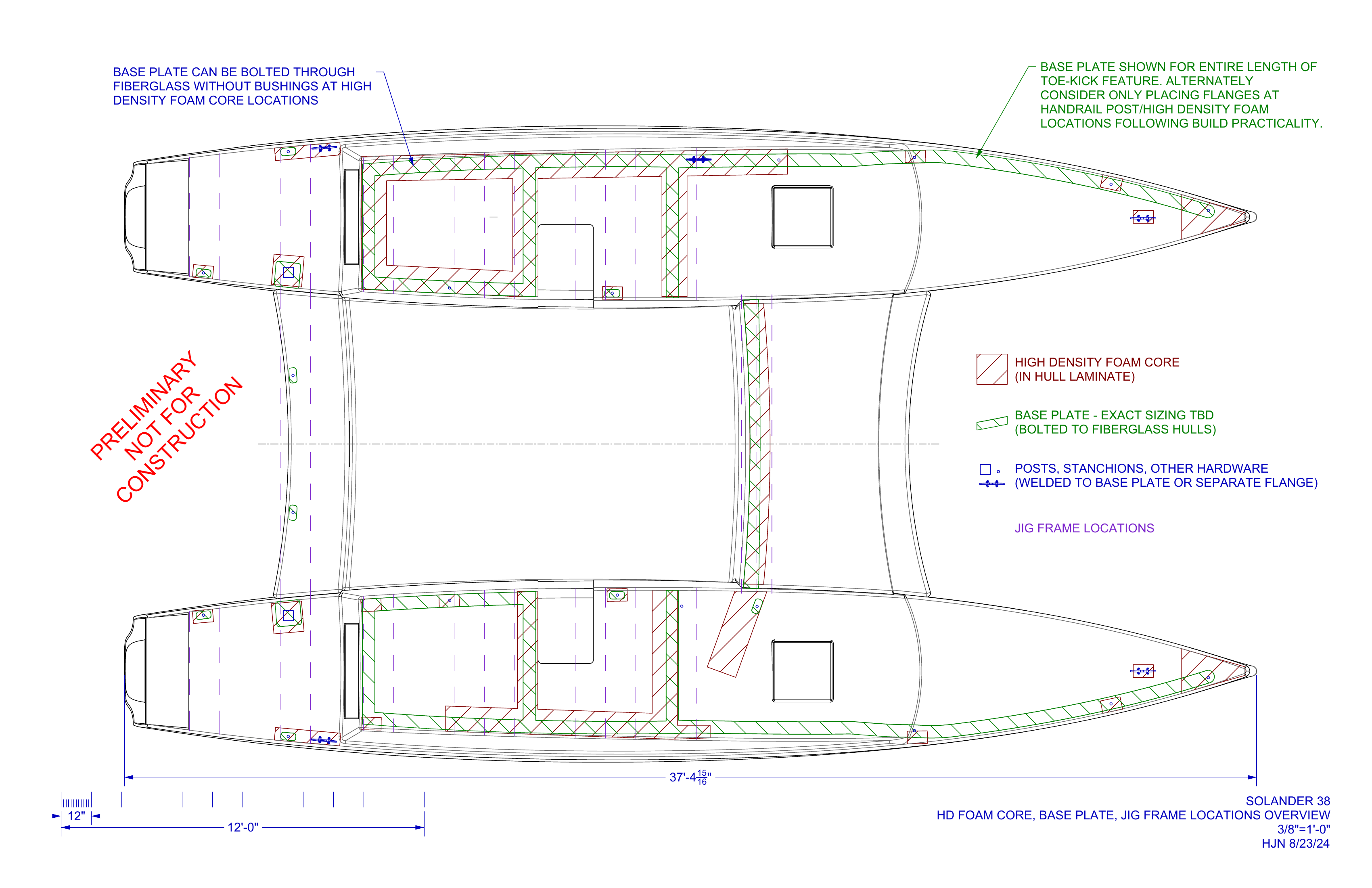
My part in the Catalyst build started with construction drawings for the aluminum superstructure. Really a communication task: to translate the nicely detailed 3D model by Eric Laukkanen, with its part thicknesses and angles and curved geometry, into the language of the shop – ReVision Marine in Port Townsend, Washington.
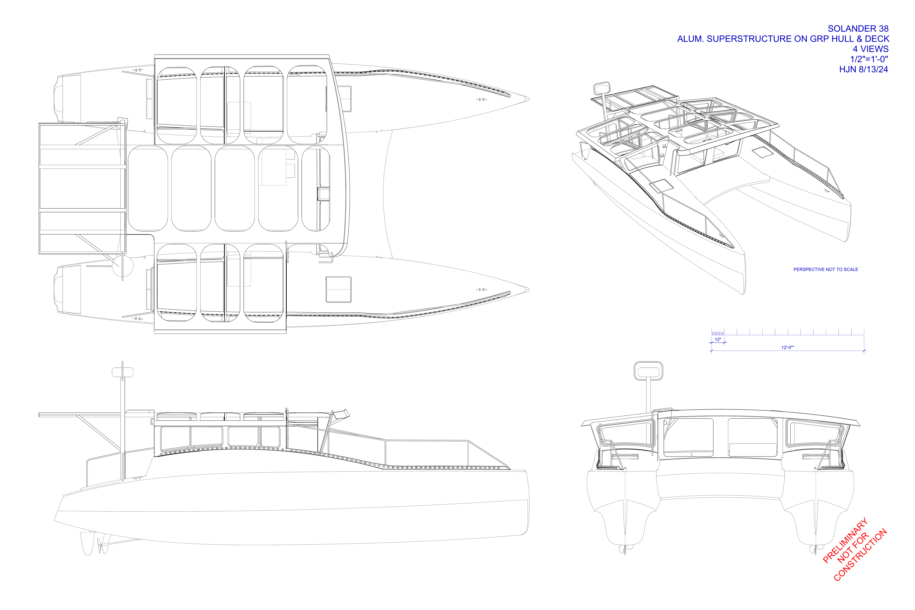
It’s impossible to explain something without understanding it, so I spent plenty of hours zeezling and zoozling the 3D model on my computer screen, measuring distances, grokking the structure and geometry, before creating some simple planview, profile, elevation, and perspective views. I use Rhino 3D for 3D modeling and 2D drawings. I printed the drawings on 36” by 24” paper, rolled them up with a rubber band inside a black plastic cylinder with a bandolier-style strap, and walked the 0.8 miles from my home to ReVision Marine.
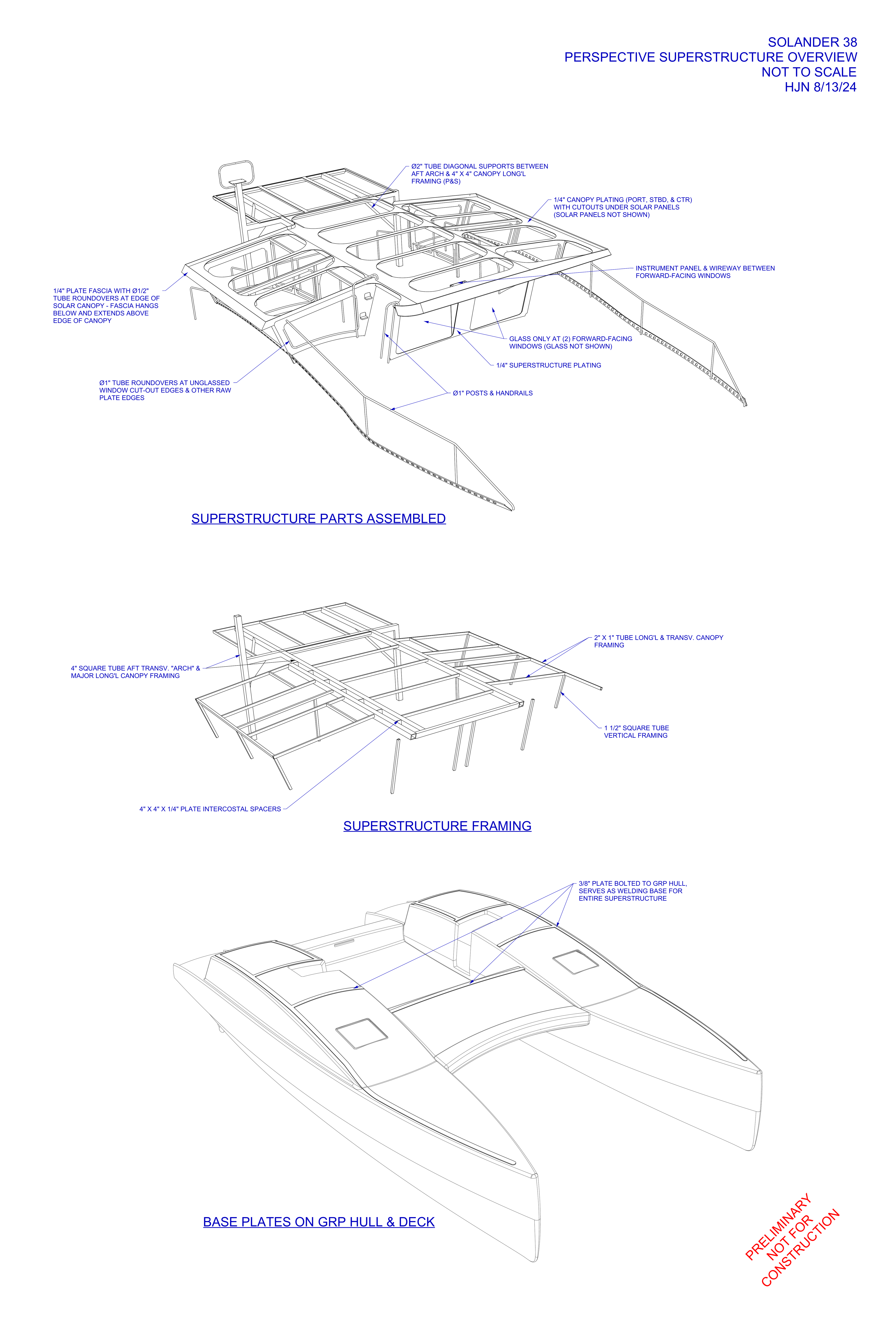
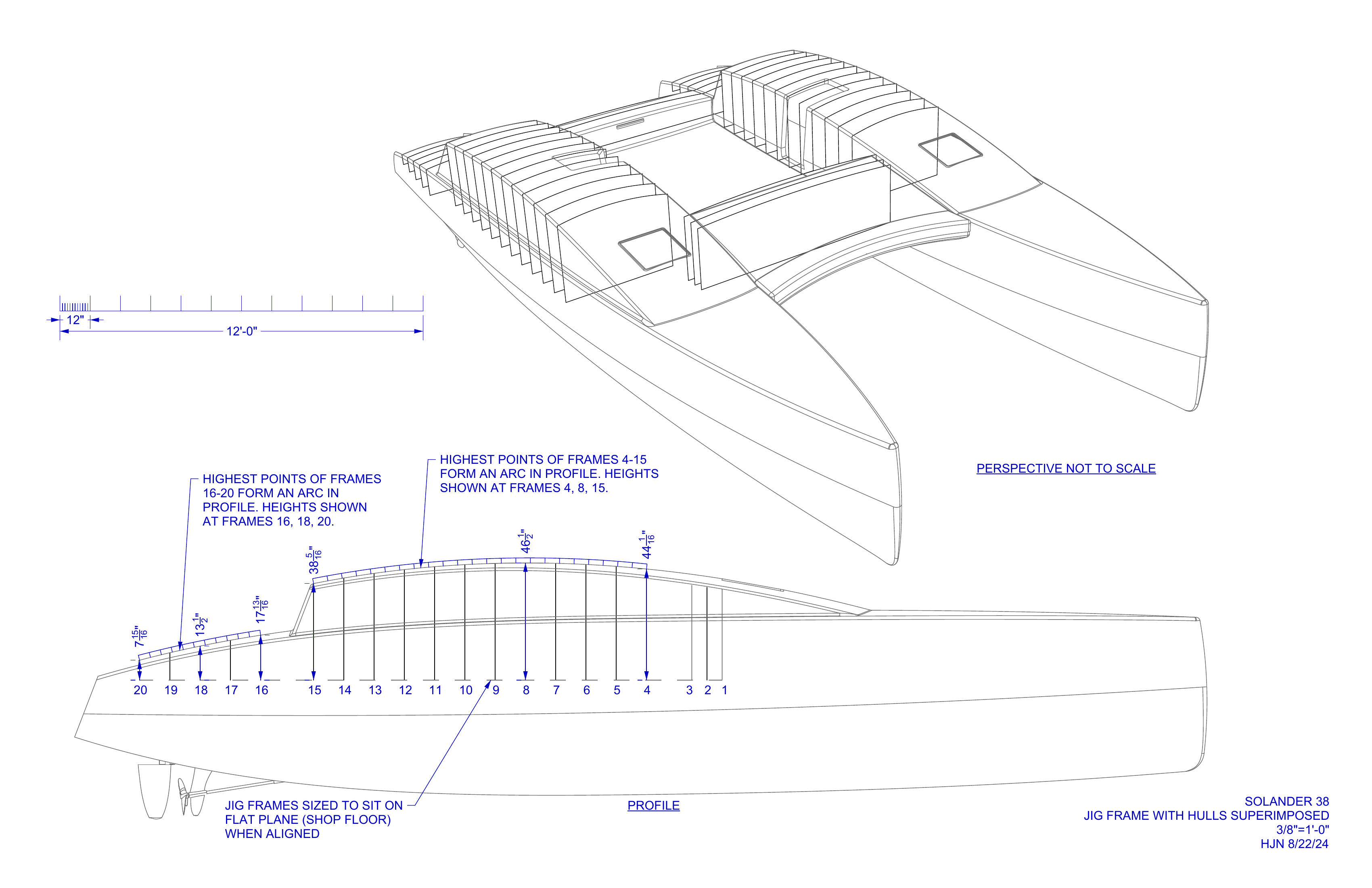
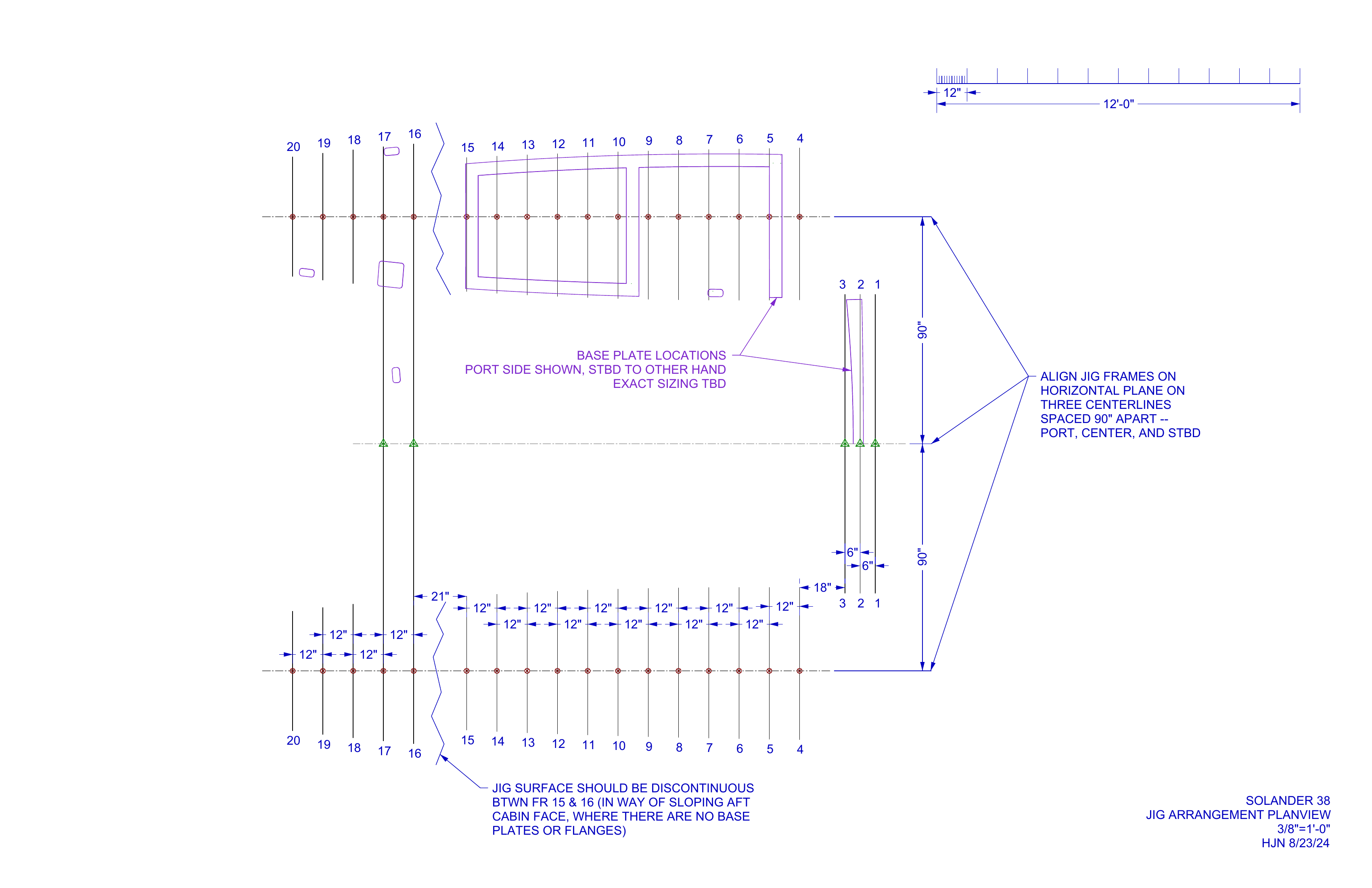
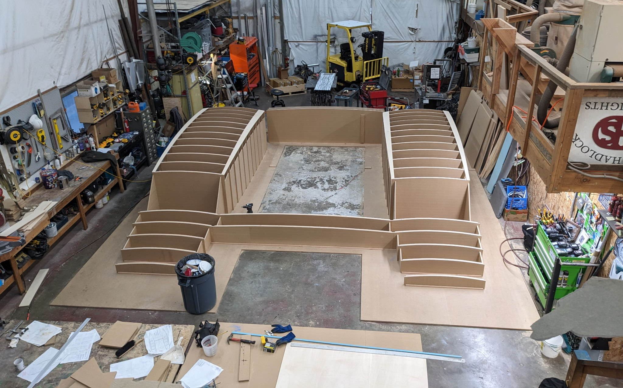
I dropped the drawings on a table textured with hardened droplets of paint and epoxy and zeezled and zoozled them around with Greg Stupica, Mike Quandt, and Terry Nowell. Catalyst’s starboard hull dominated the shop space, glowing green and white. We talked over the paper long enough to find a starting point: a jig on which to form the superstructure’s ⅜” aluminum baseplate, designed to fit the compound curvature of the cabin tops and center beam console.
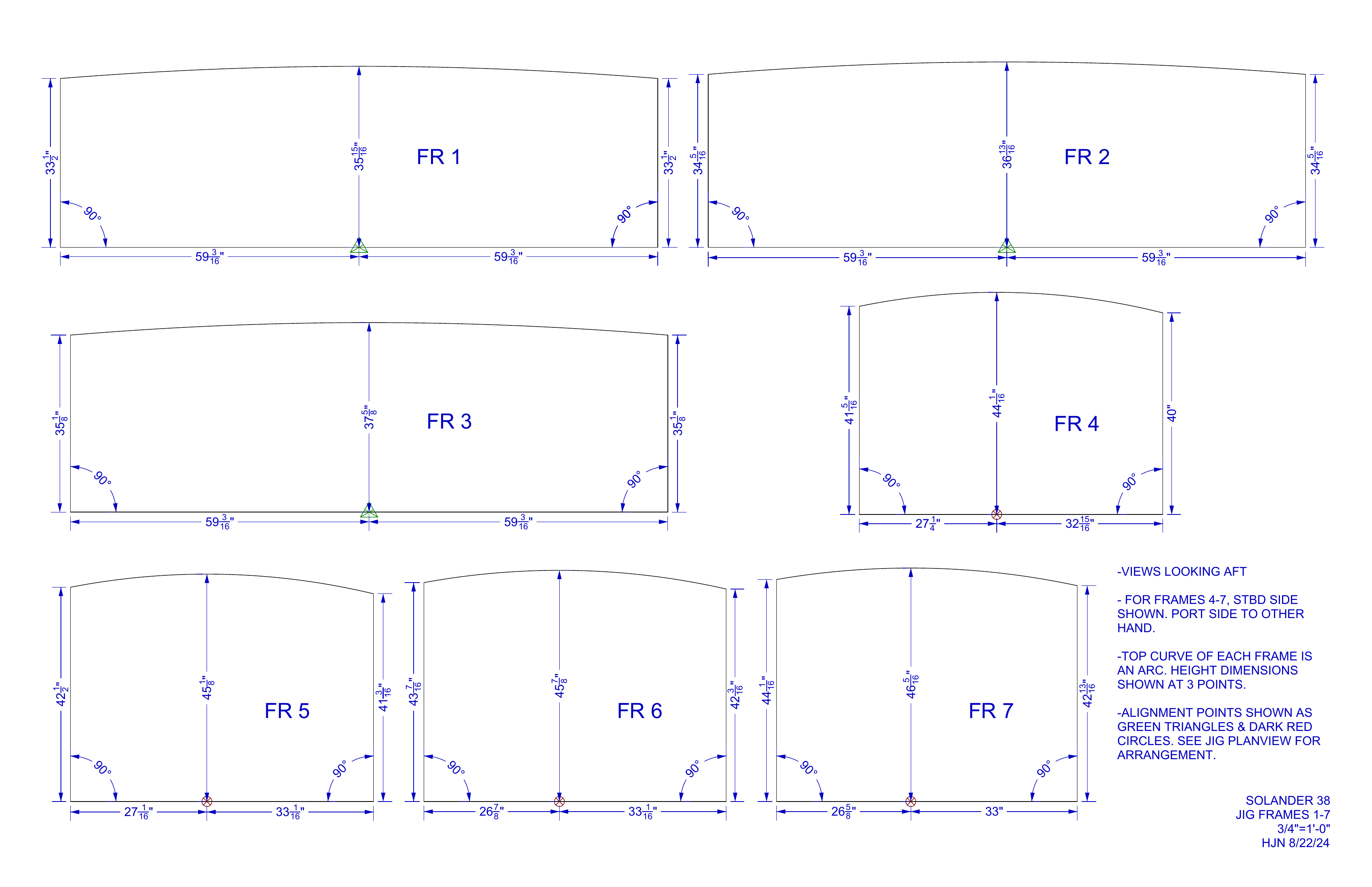
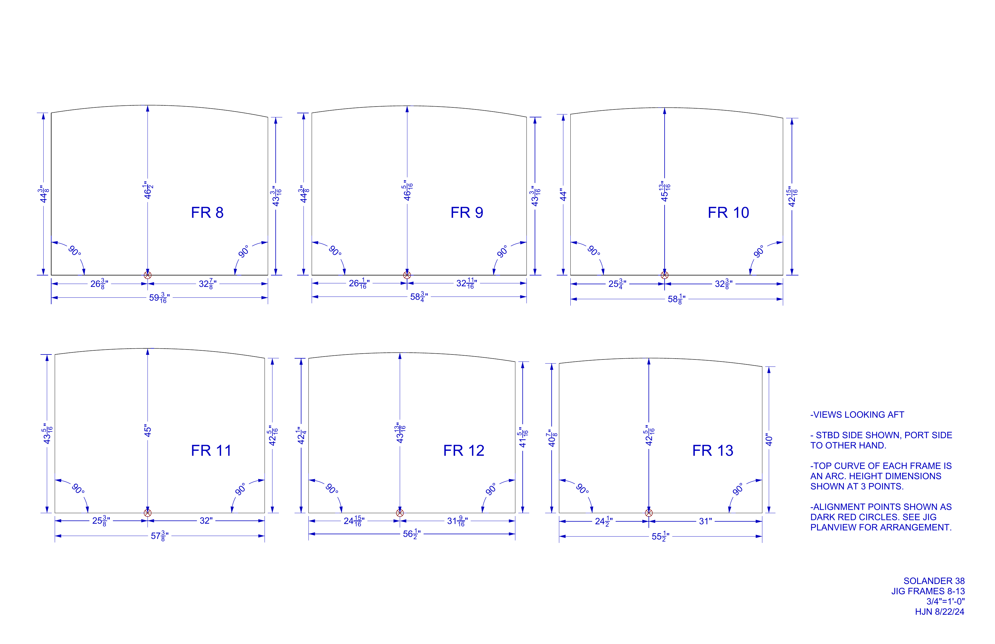
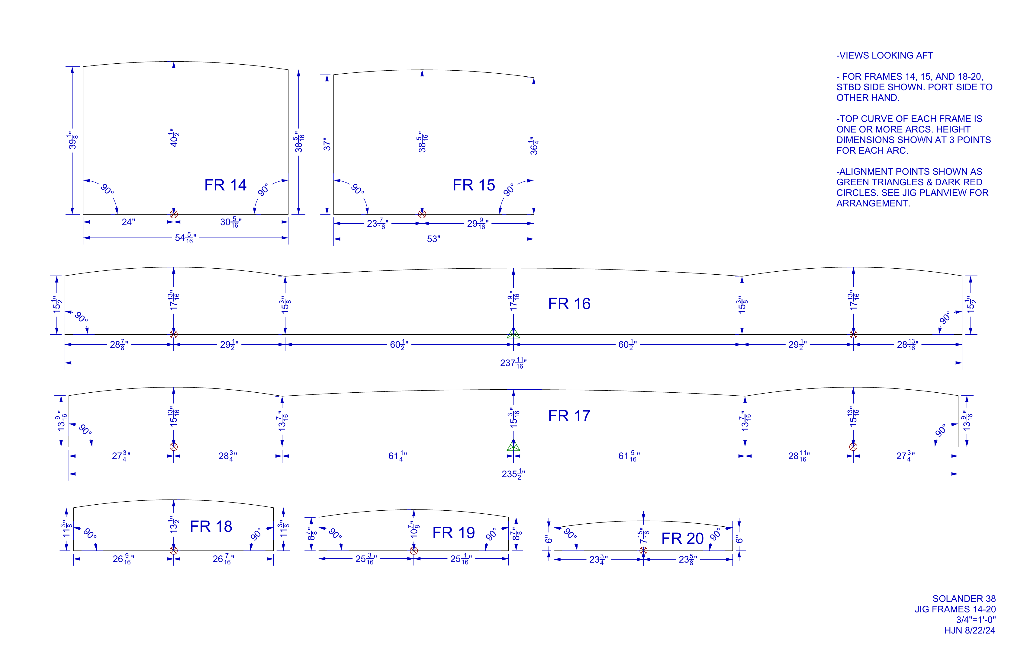
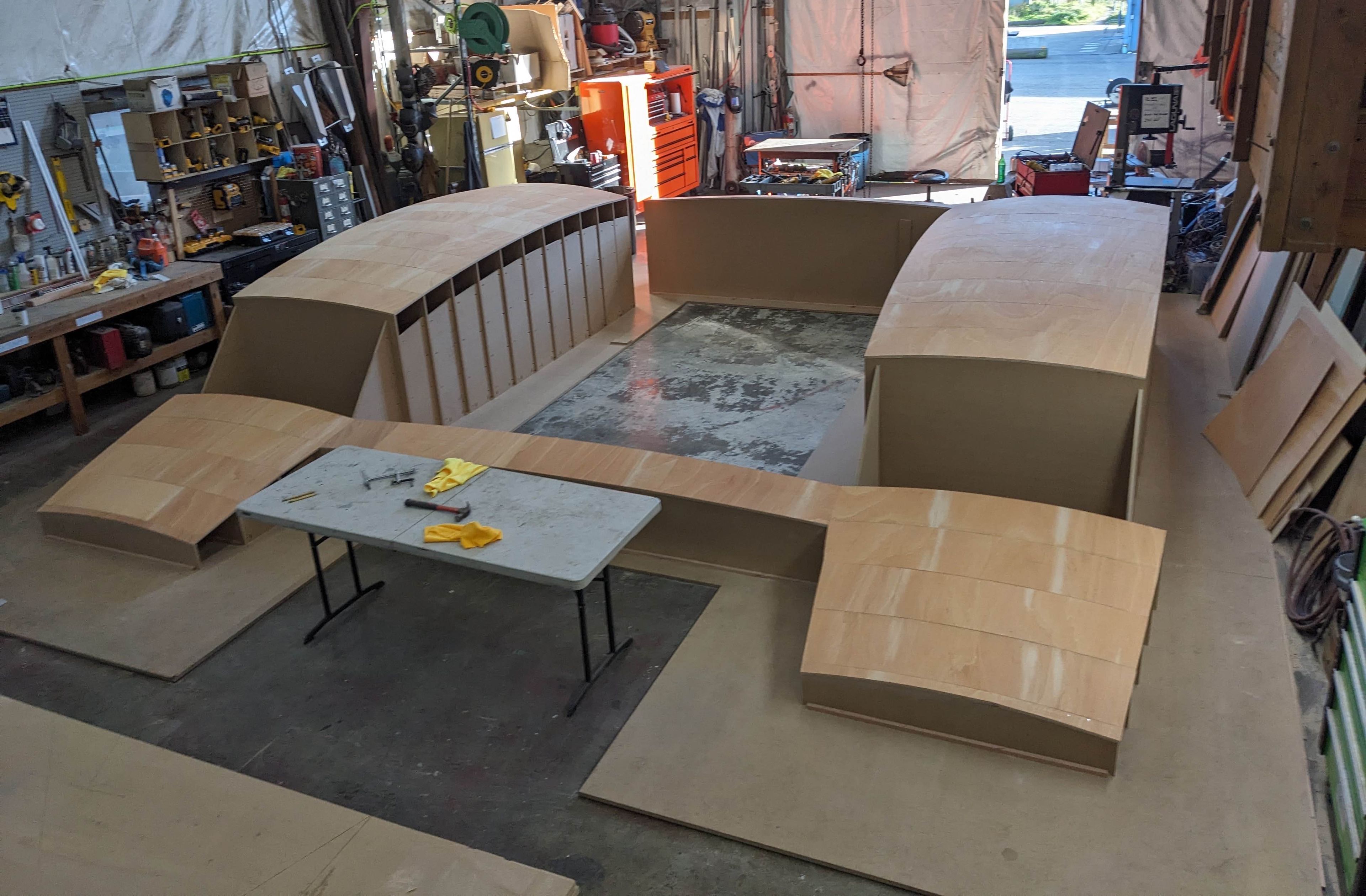
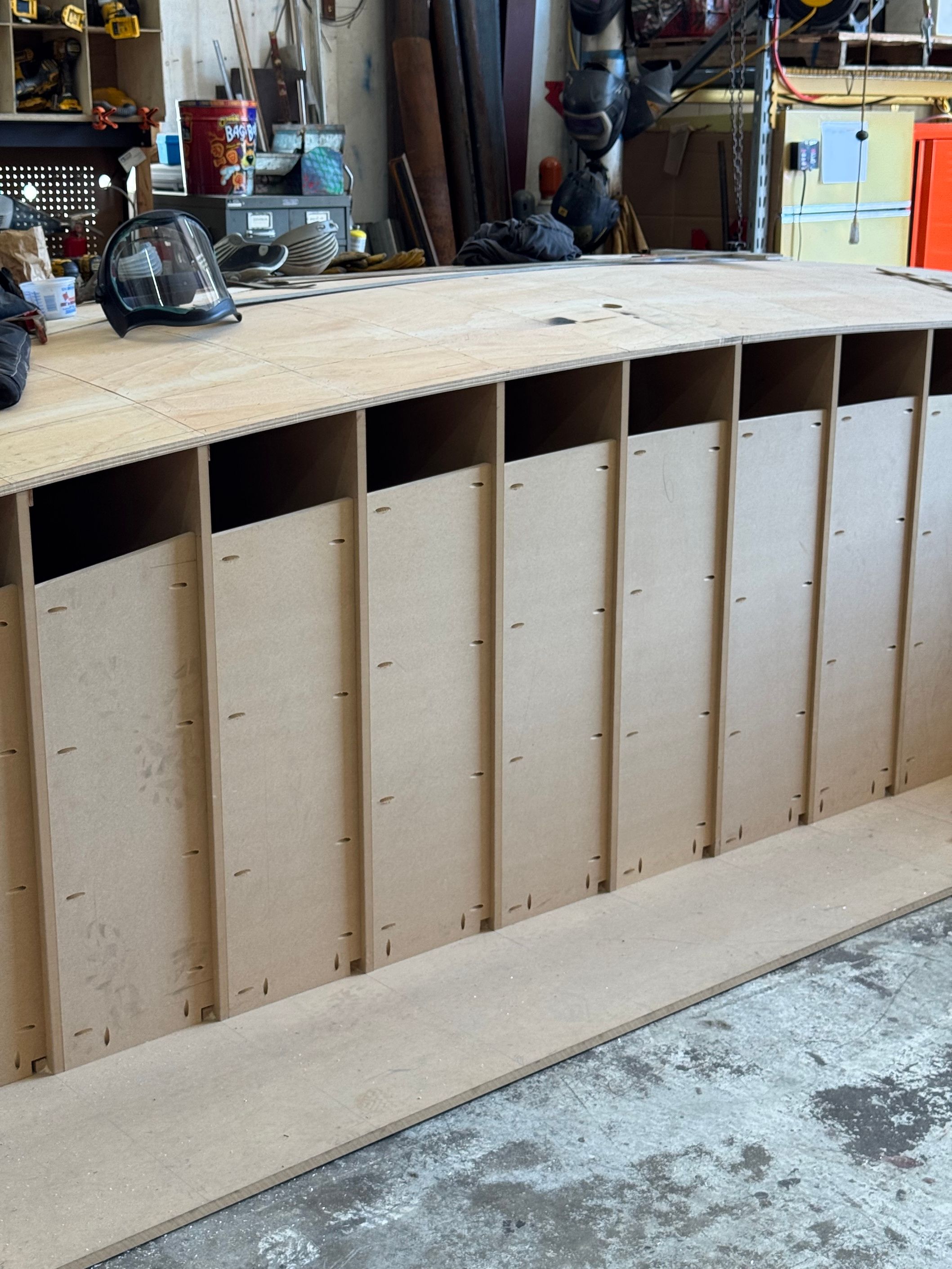
I sliced the model into transverse sections and generated dimensioned drawings for the jig frames. Greg cut the frames from ¾” OSB, squared them up on a base on the shop floor, and skinned the top with longitudinal strip planking and flexible ⅛” plywood. Together, we marked out the footprints of the superstructure baseplate on the jig, and Greg transferred those marks to patterns to cut strips of ⅜” aluminum.
Jig booklet
The initial plan was to weld the entire aluminum superstructure on the jig, then move the dang thing onto the hulls. This made sense for two main reasons:
- When we first sat down to plot it out, only the starboard hull had arrived at the ReVision shop.
- Welding up all the framing and plating someplace else would protect the hulls from sparks and heat.
Superstructure jig
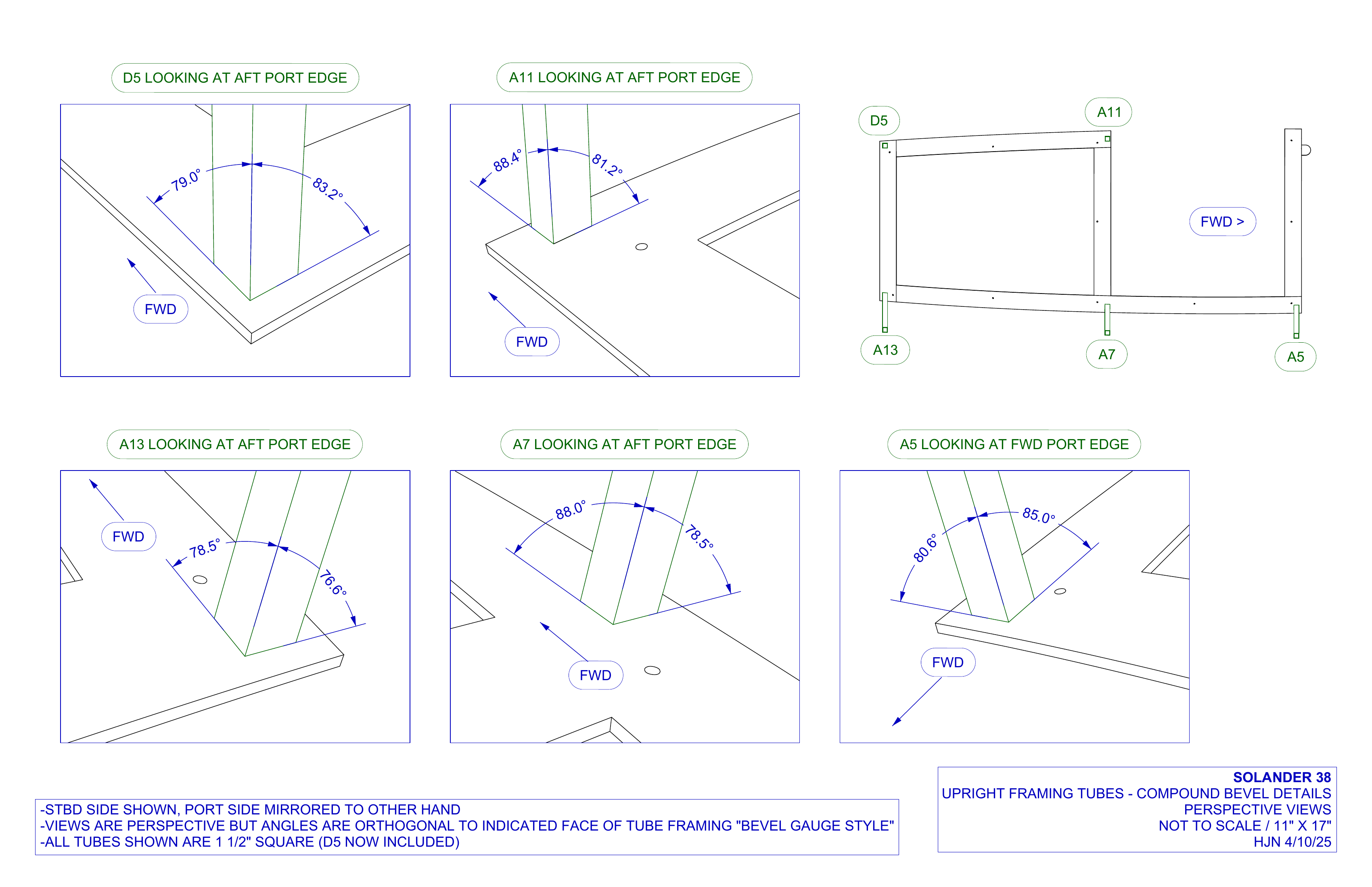
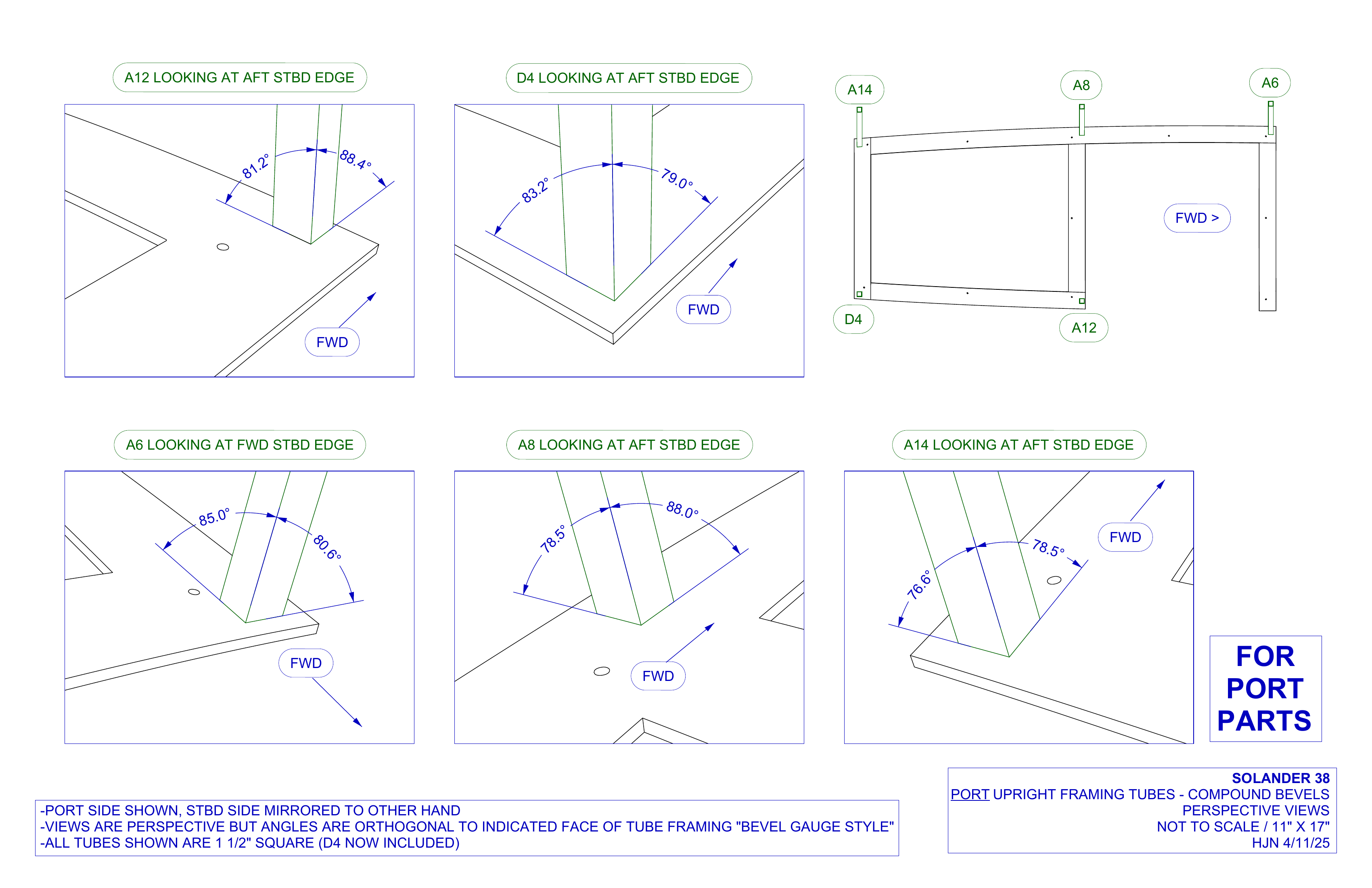
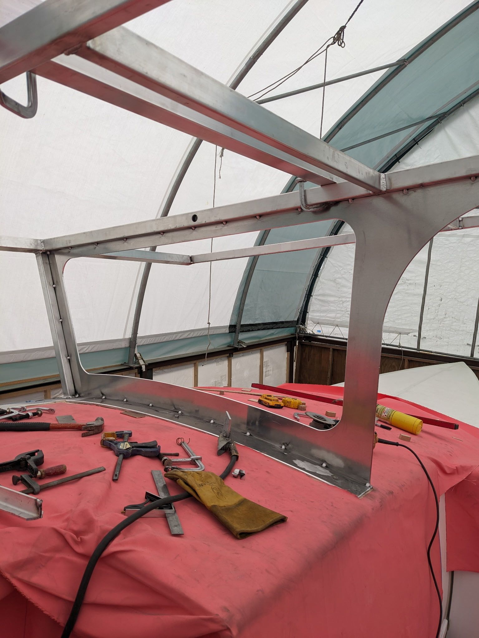
But building a complex aluminum part to perfectly fit a compoundly curved surface looked more and more like an exercise in overconfidence, even with the benefit of the 3D model. Ultimately, we compromised. Baseplates were formed and welded on the jig, with vertical stanchions tack-welded to the baseplates. At this point, I made a cartoony little drawing I’m particularly proud of: a set of compound bevel angles for the vertical stanchions (vertical used loosely here; the outboard ones lean outboard), measured and shown in perspective straight from the 3D model. The fit ended up nearly perfect.
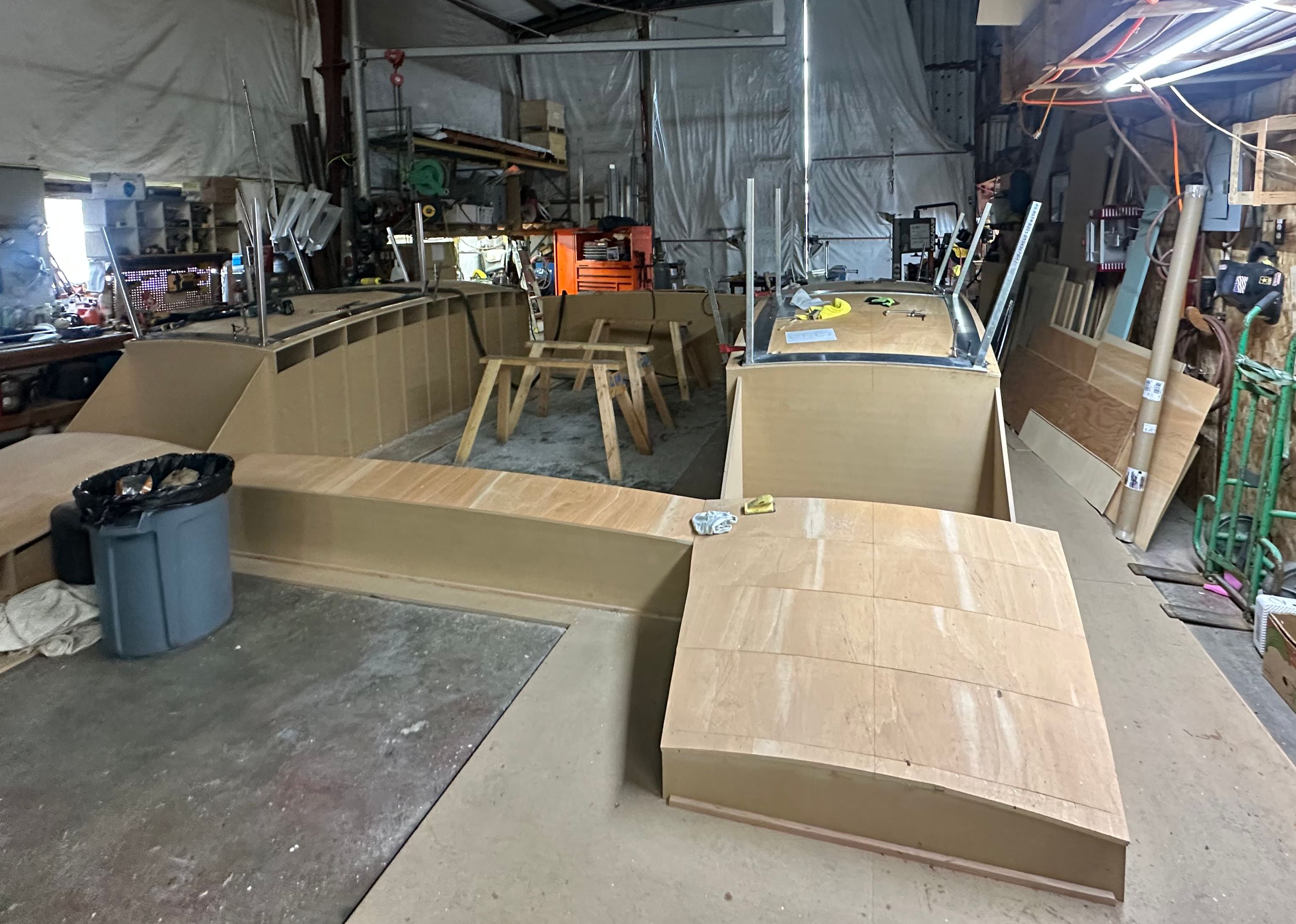
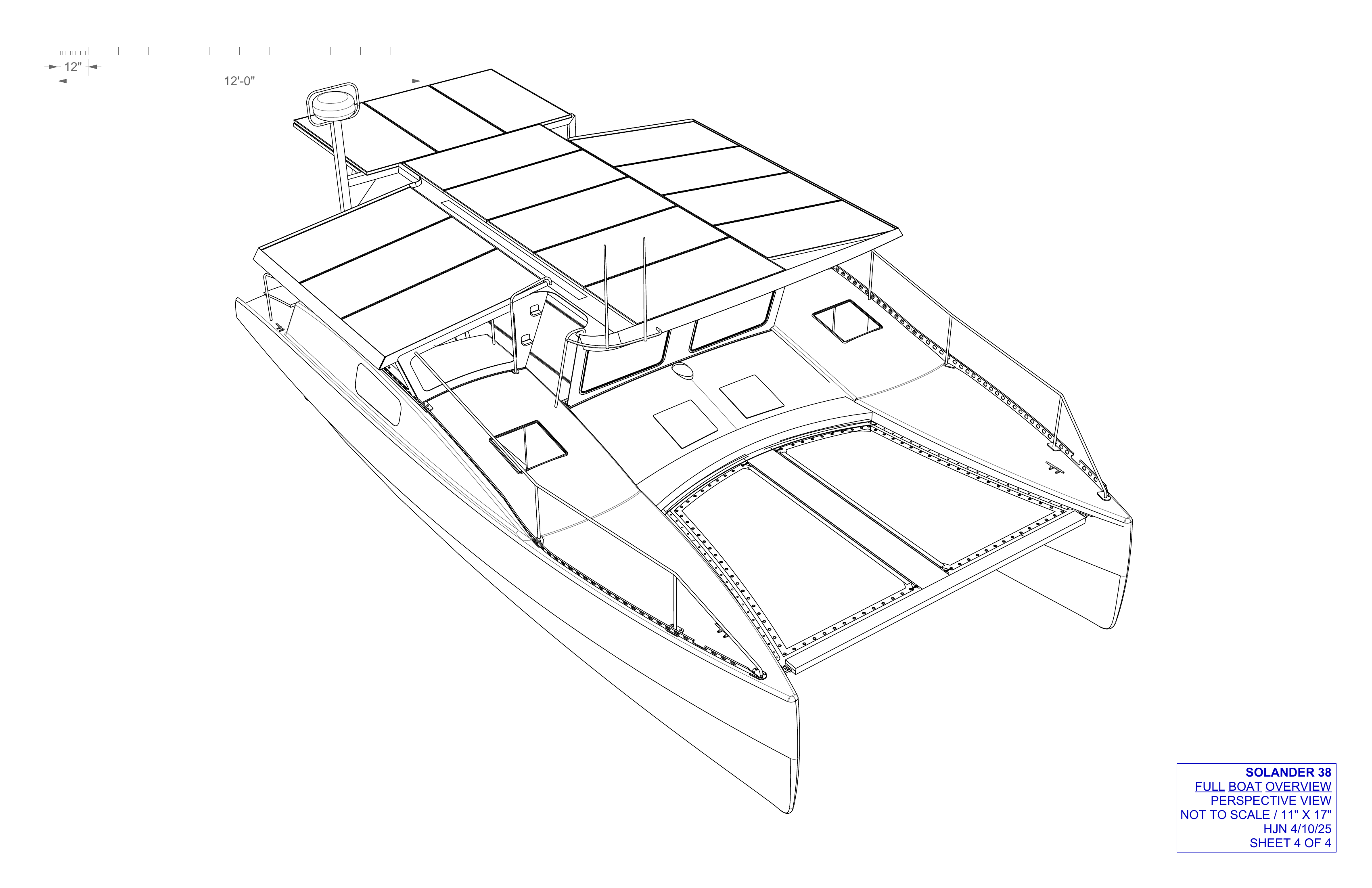
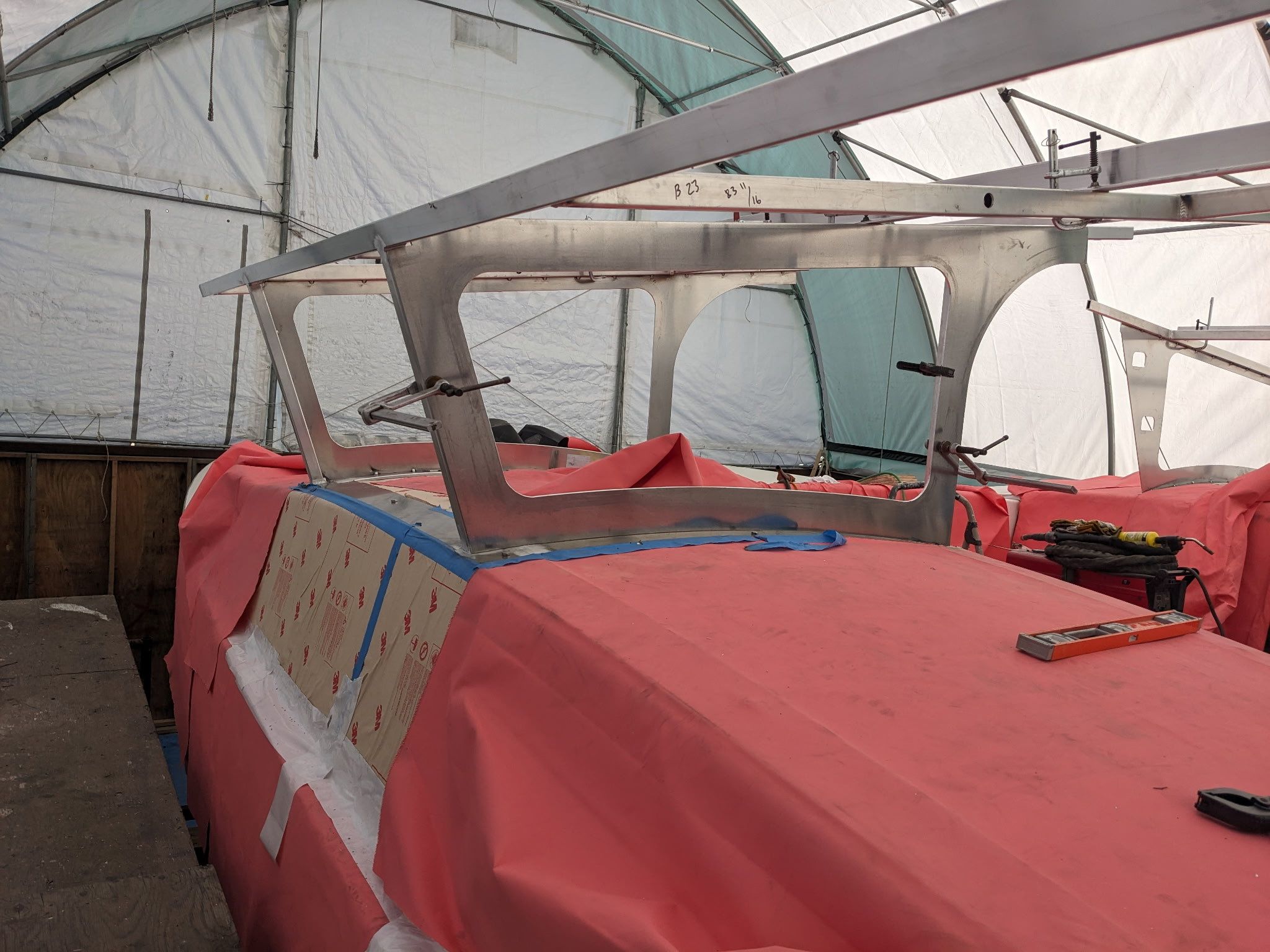
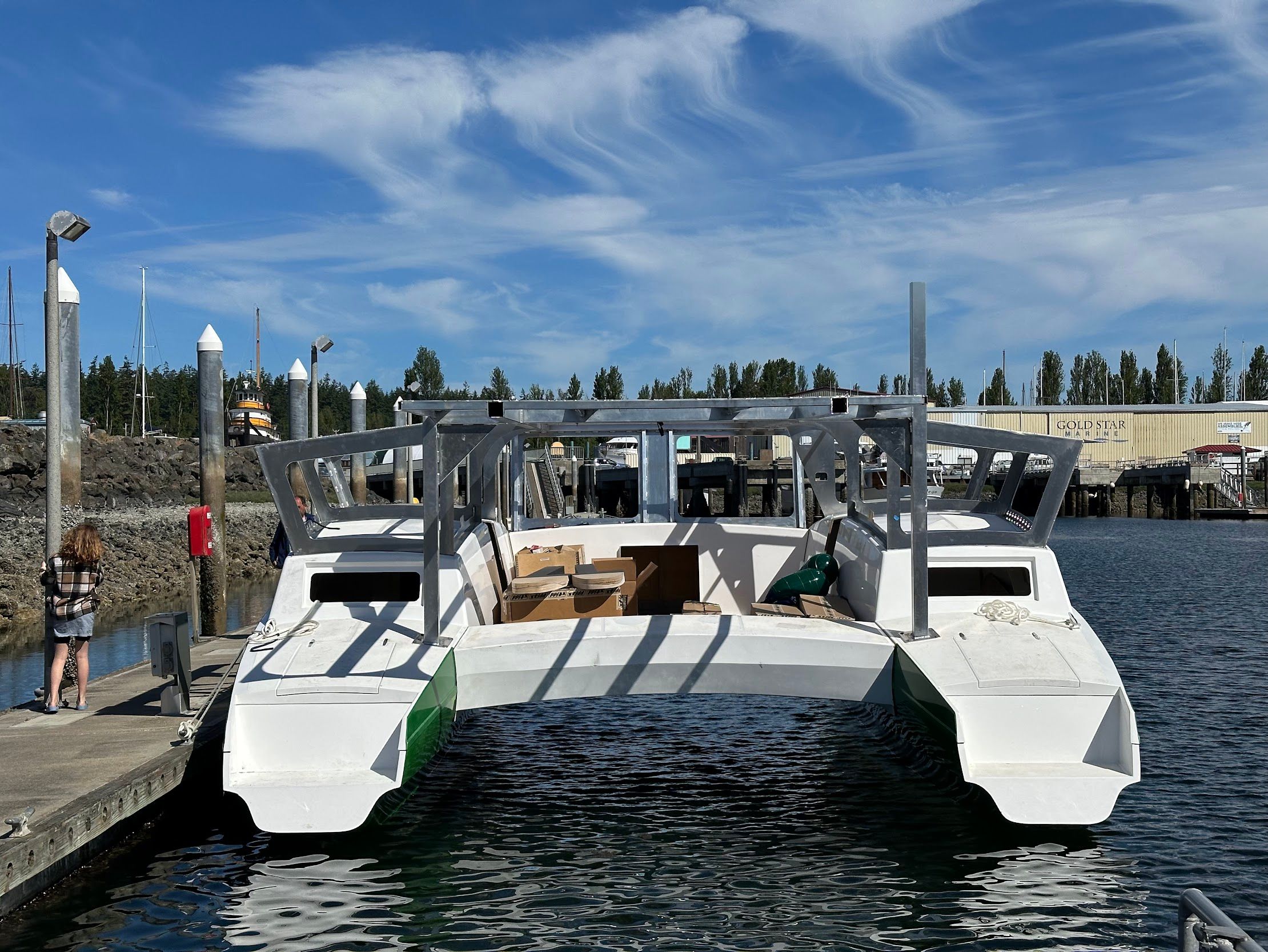
The baseplates bristling with their square tube stanchions moved up and onto the hulls, bedded in heat-resistant sealant, fastened with bolts where the hulls’ composite sandwich was reinforced with high-density core, and swathed with welding blankets to protect exposed hull. By this point, I’d released a preliminary planset with all the superstructure parts laid out and dimensioned – rectangular tube framing, Aluminum 6061; and ¼” plate panels, Aluminum 5052. Working from those drawings, with alterations and additions where necessary, the ReVision team cut and welded the thing to life. Greg scribed edges and built patterns for the big windowed plates on the outboard edges of the baseplates and for the transverse bulkhead plates. The three big longitudinal 4x4s went up with the vertical 4x4s and their small square baseplates on the aft decks, and then came the transverse 1x2s and the forward-facing windscreen on the center beam, connecting the port and starboard portions of the superstructure together in the center.
We’d floated back and forth the idea of CNCing parts from the start, and ultimately landed on a compromise (see the pattern?). To get the fit just right, all the parts that landed on the baseplate were hand-scribed and hand-cut in the shop. The canopy plates, which had been sized in the model to tightly accommodate the solar panel arrangement, were CNC cut by Brandon Davis at Turn Point Design in Port Townsend. With all the other framing and plating welded in place, the builders hauled the canopy plates up on top with elbow grease and forklift power and locked them in.
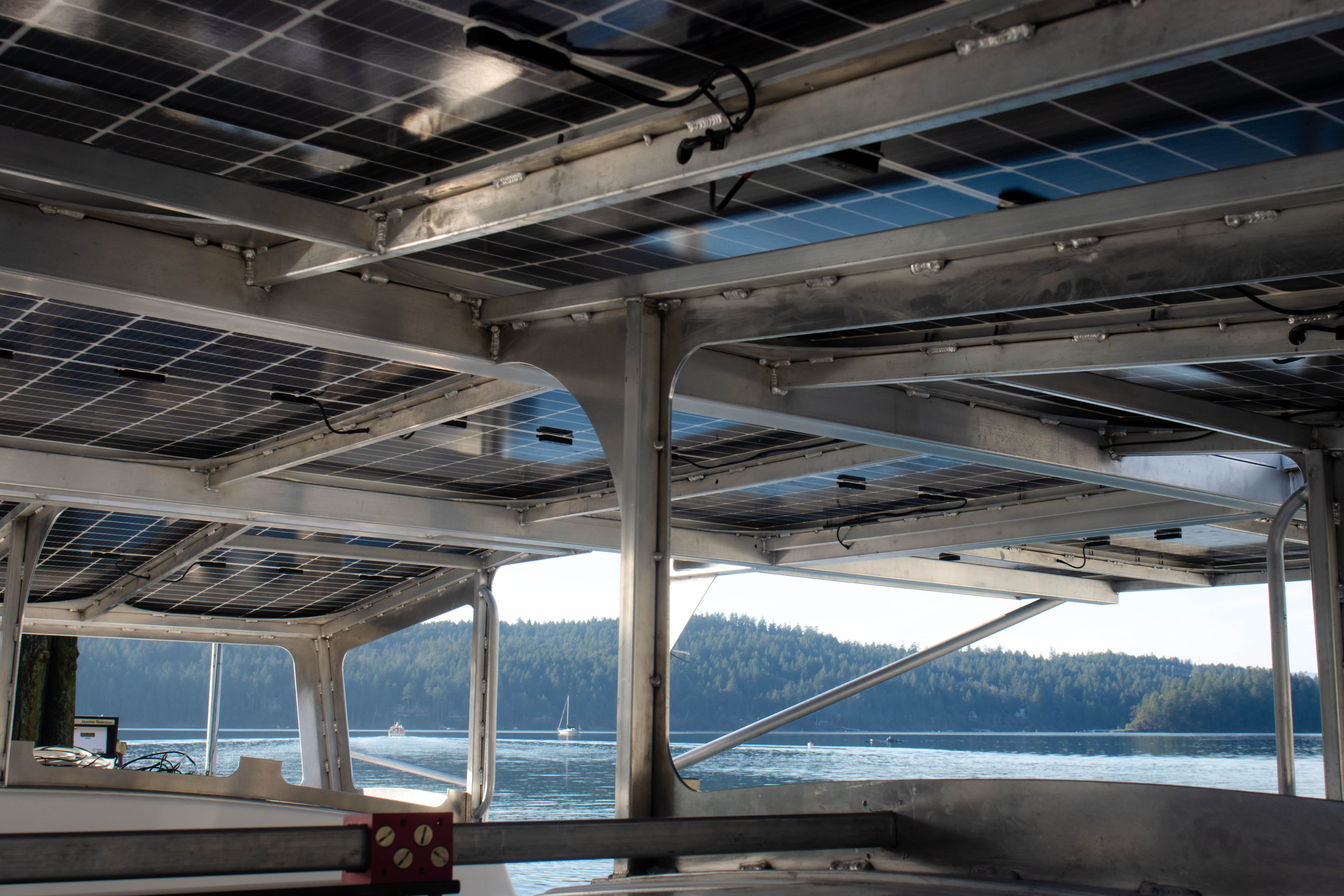
The superstructure came together through a mix of ancient and fresh techniques. Scribes and jigs and patterns, like shipbuilders centuries ago, for sleek curved edges where aluminum meets molded composite hull. Frames spaced to the 16th of an inch to fit a canopy cut directly from a digital model up top. Some of the builders told me that 16ths don’t exist, but Rhino 3D thinks they do.
For my part, I got to enjoy the luxury and the heat of an active build nearly next door. The opportunity to re-release a drawing the next day, or even the same afternoon, with minute changes. I measured angles with a digital level and held tube frames in place as Mike welded them. Don’t look at the green flash!
I’ve worked in shops building boats from fiberglass and carbon fiber, I’ve sanded graphite molds for ten hours at a stretch, I’ve screwed up the ratio on two-part interior primer and cleaned it all off and repainted it. But prior to this, I hadn’t really worked with metal or welding, so being so closely tied to the builders was a blessing of education, even as the middleman, the one turning someone else’s clever 3D design into sheets of paper to gesture over and spill coffee on. Aluminum acts differently, welds differently at different thicknesses; it springs and flexes in a way that those who work with it can predict implicitly.
As a draftsman, how do you know what to put on a drawing of a particular part built from a particular material? The people who build it know what they need, and they will tell you. You will have a better idea of how to draw the next part, or the next build. Then they will feed you lunch, send you pictures of their big orange cat, and give you a ride home in the rain.
Materials
Aluminum 5052
Easily formed or bent without breaking, with good surface quality, often used for marine shell plating.
Aluminum 6061
Well-suited for machining and extrusions, often used for marine structural members.