5–B control
Fit & clearance for steering components
Practical process of fitting steering components and installing clearance tunnels between separate compartments.
Published

Catalyst has two rudders in the port and starboard hulls, connected via three draglinks, four tiller arms, and two dummy shafts housed in the aft compartment of the center beam. When the rudders rotate, there are ten total axes of rotation – the centerline of each rudder shaft and each dummy shaft and its set-screwed tiller arm; and each of the six points where draglinks fasten to tiller arms. The angular relationships between the tiller arms allow for Ackermann steering geometry: when you turn the boat, the two rudders trace the tangents of two offset circles such that the ‘inner’ rudder, on the side you’re turning toward, makes a sharper angle off centerline.


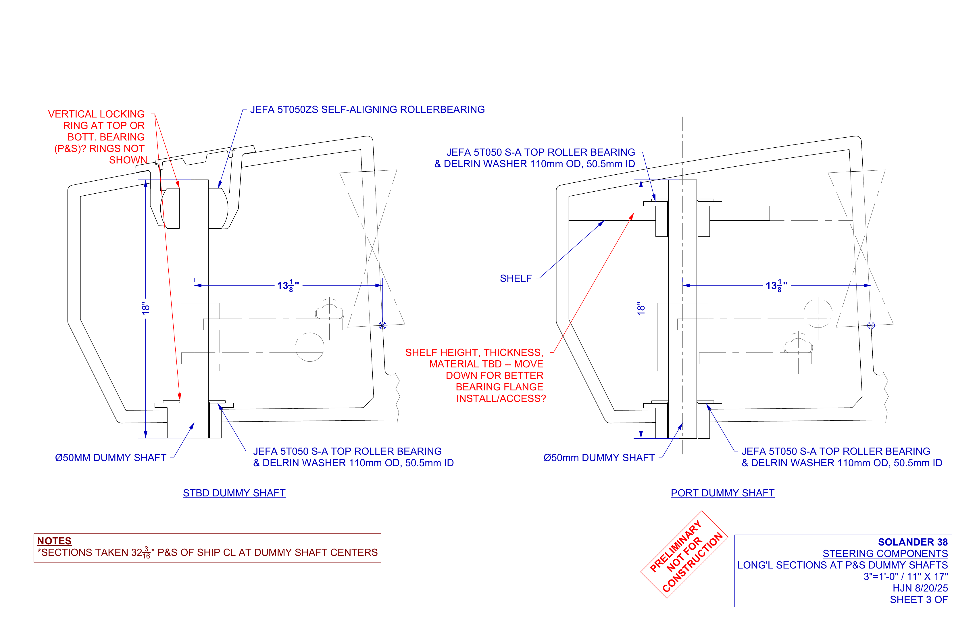
With the steering system components preliminarily modeled in the initial 3D model I received, I dove into the normal design spiral of making adjustments for fit as the hulls and center beam came together. As the timeline unfolded, we figured we’d end up installing the rudders at ReVision Marine, cut the tunnels to allow draglinks to pass inboard to the dummy shafts, and install the dummy shafts and draglinks at Canoe Cove Marina in Sidney, British Columbia. We needed to cut the tunnels in the right location to allow clear passage of the draglinks and lay the groundwork for the folks installing the rest of the steering components. So our starting point in the real non-CAD world was the rudder shafts.
The rudders: each one is an asymmetrical wake-adapted fish fin designed by Brant Savander. Brandon Davis of Turn Point Design modeled and CNC cut molds, and Dan Newland of Pegasus Composites laminated the rudders with carbon fiber skins. Dan and I made first contact when he brought the finished rudders to Revision, and from there we began a rapid-fire back-and-forth to get the rudders installed in the right spot and mark out all the key locations that unfolded from that spot.
Rudder foil & rudder tube installation


Rudder components


Dan designed, built, and installed the rudder tubes with their flared ends at top and bottom to house turcite bushings, all the while working with folks at ReVision Marine to get the propeller shaft aligned and the motors and struts installed. I fed him dimensions and drawings and answers from the 3D model, and updated the model to reflect parts as built. With the rudder tubes in place, we set to marking out the locations of the steering components and figuring out where to chop openings.

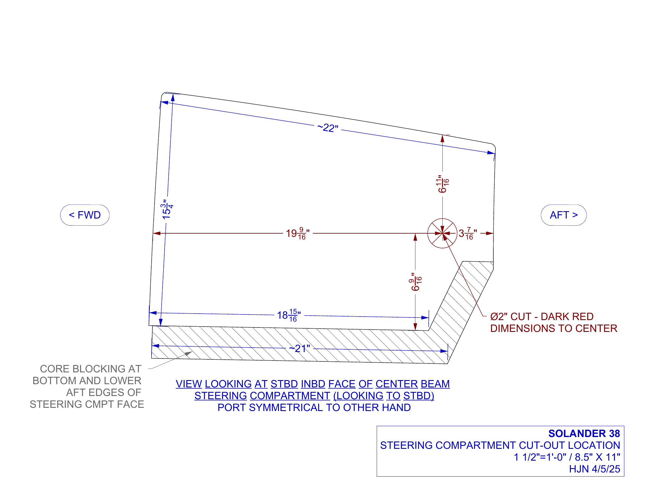
I had marked small pilot holes between the central steering compartment and the steering compartments in the port and starboard hulls, and those holes had been shot and filled with temporary bolts and washers to hold the hulls and center beam together while the adhesive from the massive glue-up cured. After the glue-up, we popped the bolts out and ran a taut string from the rudder tube center, through the pilot hole, and into the central steering compartment to get a ballpark of the draglink angle and thereby the location of the dummy shafts. Everything was an offset or an offset of an offset. Blue tape, sharpie marks, head and one hand through the center beam steering hatch, phone for a light source, zip of a welder and green flash from just outside the edge of vision – the aluminum superstructure build was in full swing at the same time. I’d uncurl and scamper to the laptop sitting on the red fire blanket on the deck to check a dimension or scooch a part, then back in the hole.
I’d been fiddling with the steering components in the 3D model to be sure I understood how they’d move as the rudders rotated. Compared to the ‘rudders centered’ position, the port and starboard draglinks would both move aft and inboard a couple inches when the rudders swing either hard to port or hard to starboard. This was an unintuitive revelation to me, and it basically meant that ‘rudders centered’ was the forwardmost position for the draglinks in their passage through the tunnel location. We needed to allow comfortable space aft of that to allow the draglinks to move freely.
Once we were reasonably satisfied with the prospective location and movement of the draglinks and pretty confident that everything would fit in the space, Dan started chopping. I had it easy compared to him. Tyvek suit, angle grinder, crouched in the outboard steering compartment in the small space between the steering shelf and the bulkhead. He cut approximately rectangular openings, gnawing off material around the pilot holes, through the beefy sandwich laminate of the hull and the center beam, into the broad cambered central steering compartment. He also had to nick notches into the bulkheads that formed the forward faces of the port and starboard steering compartments – the draglinks had to pass through that way, no way around it in the tight geometry.
With slightly oversized openings cut there, Dan prepared to install the fiberglass tunnels he’d built: rectangular in section with radiused corners, trimmed to a weird trapezoidal shape in planview so they’d re-seal the notched bulkhead without protruding too far into the central or outboard steering compartments. To set them in the right location for actual adhesive installation, Dan worked up a clever jig made up of a two-by-four that slid into a block that fit snugly inside the tunnel piece, with holes drilled at both ends of the two-by-four. The distance between holes on the two-by-four matched the draglink span between fastening points to tiller arms. Add two four-by-four blocks with drill-pressed holes to support the two-by-four at both ends at the prospective height of the draglink, with loosey-goosey drop-in bolts to hold it all together. I cut the four-by-four blocks, and I think I did a pretty good job, A- or maybe B+. The whole jig assemblage could come apart and slide out once the tunnel was set with adhesive, for re-use on the other side of the boat. We did the port side first.
With the steering tunnels installed we were able to pass the actual draglink parts through and see them in place, both as a reality check for distances between rudder & dummy shafts, and to prove that the 72” long parts could actually be maneuvered into position in the confines of the steering compartments. The final control point or “out” was the center draglink, which hadn’t been ordered yet. Its exact length could be a product of the final geometry of all the other steering components grasping inward from both sides. A keystone cut to fit.


Materials
Aluminum 6082
High machinability, weldability, and corrosion resistance.
Carbon Fiber
Stiffer and greater strength-to-weight ratio compared to fiberglass, but less resistant to impacts.
Composite Sandwich
Closed-cell foam core between inner and outer fiberglass laminate.
Delrin
Strong low-friction thermoplastic for bearings and bushings.
Fiberglass
Lightweight, strong, and moldable.
Stainless Steel
Higher corrosion resistance and strength than aluminum, but much heavier.
Turcite
Strong, self-lubricating, low-friction thermoplastic for bearings and bushings.